
It’s been over a month since my last post but fear not, work has been slow but steady and now I’ve got something to show to you as well as something I hope some modellers building A-10s will find useful.
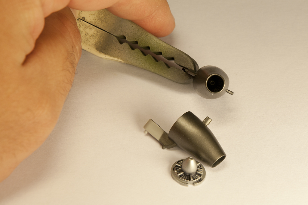
Exhausts were painted Alclad Exhaust Manifold while the compressor faces were painted Alclad Aluminium and washed with the Black Detailer wash – they’re not that bright in reality but since they’re hidden in the dark tubing of the exhaust it’s the only way they will be seen a little from behind. Call it artistic freedom if you will 😉

Insides of the nacelles were heavily washed with Flory’s Dark Wash and wiped… On reference photos they appear to be grey with dark staining but since little of them will be seen I think this effect will be sufficient.
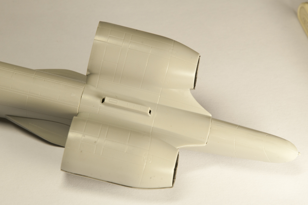
Nacelles to fuselage join appeared good enough not to produce further nightmares. However, I’ve had many problems keeping engine nacelles together – the fit was far from good and the plastic on the sides is so thin that the join breaks at just a little pressure to the surface. This prevented me to rivet the rear conical part of the nacelles. I also tried raised rivets from a HGW company, but they appeared too thin and dissappeared under a test coat of primer while removing the carrier film, removed many of the rivets with it. This forced me to employ my RaduB’s Rivet-R on all the areas.
MODIFICATION / UPGRADE
As I’ve mentioned before, Italeri’s (Revell packaging in this case) A-10A represents an early variant that could be built up to Desert Storm era. Anything newer, including grey camo versions, have to be updated. I was working on photos of the real machine that landed in Skopje on that faithful day, to try and represent mainly the sensor suite she was equipped with.
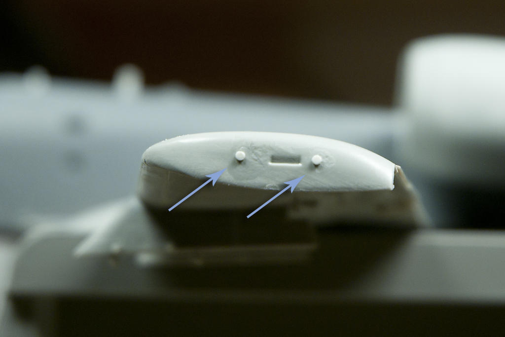
The kit comes with exposed vents, yet they received the covers later in their lives (and lost them again with C version). They were made of styrene, cut and sanded to shape and exhaust holes carved out. When they were built I noticed that Italeri placed the “grill” panel too high for a few milimeters – causing the smaller cover to be in the center of the bigger one instead of forming sort of a number 7 figure.
Another two circular sensors come attacked at the wingtips, each side of the navigational light.
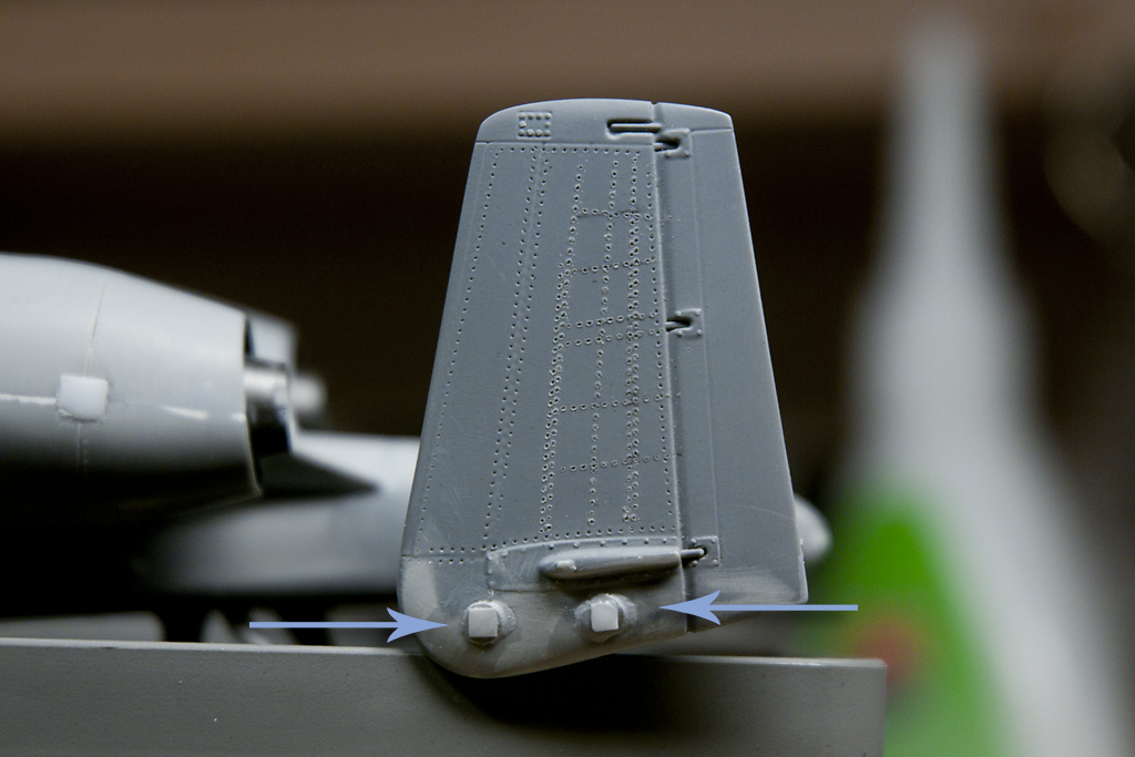
The two antennas on the tail were made by cutting square pieces of styrene and mounting them on Mr. Surfacer 500 base.

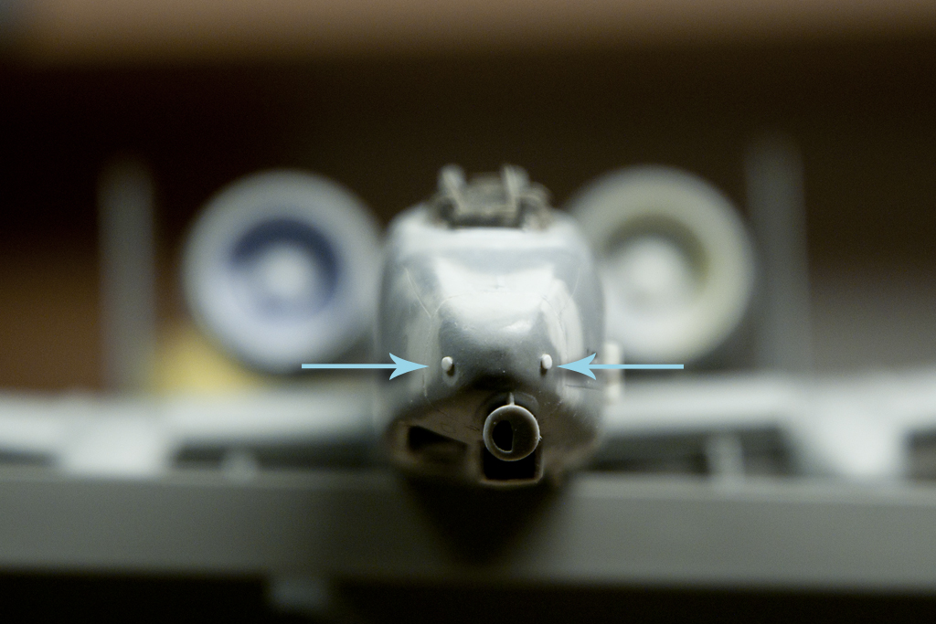
Circular AN/ALR-69 RWR antennas were placed on the nose and tail

Blue arrow shows at the antenna, which was originally there, but there was no circular pedestal for it so both had to be made new. Lower red arrow shows at the position where a bump was removed, which I persume was meant to be a tail light, while the sideways pointing arrow shows the position of the removed boxy AN/ALR-46 RWR antenna (replaced with those smaller circular ones).

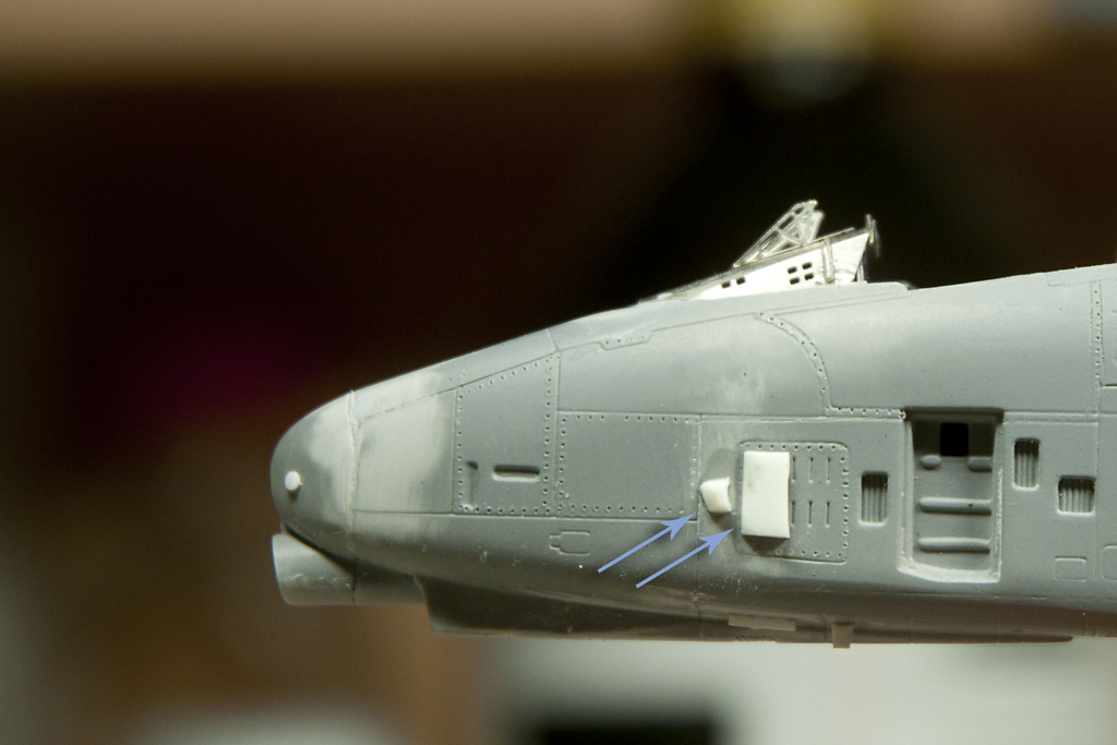
Red arrows in the insert show the box RWR antenna, similar to the one on the tail which needs to be removed as well as the antenna on the gun cover, which needs to be moved from there to the side of it, as shown with the blue arrow. There’s also a short long antenna mounted in front of it.

momak svaka cast,samo napred,pratim i uzivam
pozdrav Djordje
Hvala!